
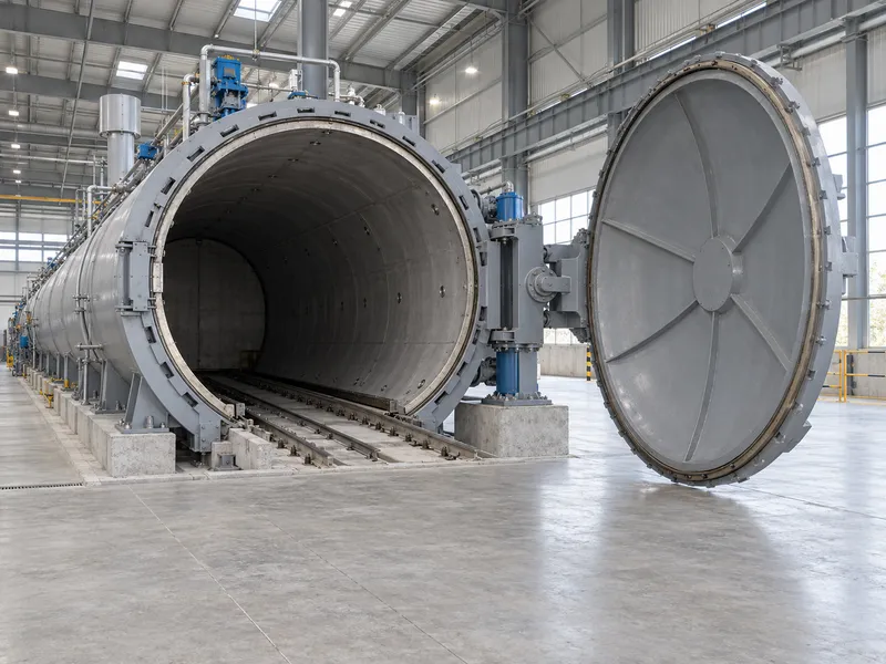
AAC autoclave door design affects more than the space directly in front of the vessel. A side-opening door needs a clear lateral movement envelope, while an upward-opening arrangement introduces overhead mechanism and access requirements. Compare both options on a layout that includes loading movements, neighboring vessels, service work and component removal before selecting the door configuration.
Neither arrangement is automatically the most compact or easiest to maintain. The answer depends on the actual mechanism, vessel spacing and building geometry. Require dimensions for the full door travel before judging claims about a compact installation.
Which Door Characteristics Need to Be Separated?
Opening direction, locking arrangement and actuation describe different parts of the design. A door that moves sideways may still use a powered locking mechanism, while another design may combine different manual and powered functions. Specify the complete assembly instead of comparing one feature in isolation.
Runding’s AAC autoclave information describes side-opening and top-opening arrangements, with different actuation options subject to the supplied configuration. Use those descriptions to start the layout discussion. The order should identify the selected mechanism and its actual dimensional requirements.
The configuration also needs to suit the loading concept. A vessel loaded and unloaded from one end presents different traffic questions from a system with access at both ends. Confirm the proposed flow before reserving the surrounding floor space.
What Does the Movement Envelope Include?
It includes every position occupied by the door and its supporting mechanism during normal movement. Show the parked position, projecting arms and any counterweight travel where relevant. Nearby guards, platforms, pipes and building columns must be checked against that complete envelope.
The movement drawing should also distinguish the area kept clear for operation from the space used for service work. Show both allowances on the layout, even where they occupy some of the same floor area. A door can move freely while still leaving insufficient room to maintain its supporting components.
When Can a Side-Opening Door Fit the Plant Layout?
A side-opening design can suit a layout with adequate lateral clearance and a convenient parked position beside the vessel entrance. Its suitability depends on the actual swing or supporting-arm geometry. The buyer should check both the front approach and the side into which the door moves.
Consider a row of parallel vessels rather than a single isolated unit. A door parked beside one entrance may occupy space needed by the adjacent vessel’s operator, service access or loading equipment. Review the intended combination of open and closed doors during normal production.
Confirm the proposed opening side before civil and pipework arrangements are fixed. Changing it later may affect the supporting structure, controls, guards or surrounding equipment. Do not assume that a left-hand and right-hand arrangement can be exchanged on site without manufacturer review.
Which Access Routes Need to Remain Available?
Mark the routes used to reach instruments, valves and designated service points. Then inspect how those routes change when the door is parked open. A path drawn through the door envelope is not continuously available simply because it appears clear with the vessel closed.
Separate regular personnel access from the travel path of loading equipment. The machinery and site designers should establish the required guarding and access arrangement for the specific installation. Procurement drawings need to reserve that space before equipment placement becomes difficult to change.
What Changes With an Upward-Opening Arrangement?
An upward-opening design can reduce some lateral conflicts, but it transfers attention to the space above and around the vessel entrance. The mechanism may require a supporting frame, lever travel or counterweight clearance. Its highest operating position must be checked against the building and other services.
Review roof members, overhead pipes, cable trays and any crane route in the same elevation drawing. A clear plan view cannot reveal these conflicts. Include the mechanism’s movement and the access needed to inspect its upper components.
The supplier should identify how major parts are supported and removed for maintenance. An arrangement that fits beneath the roof during operation may still need additional lifting or removal space. Reserve the required access in the initial layout instead of treating it as a future maintenance problem.
Does Less Floor Area Mean Easier Maintenance?
Not necessarily, because the position of service points matters as much as the footprint. Some tasks may move higher above floor level or require a different access arrangement. Compare the supplier’s service requirements for the actual designs offered.
Request a description of the access equipment and lifting provisions assumed in the proposal. Confirm whether these are included in the supplied package or provided by the plant. That distinction can affect both the building layout and the installation budget.
How Should Loading Equipment Be Checked Against the Door?
Check the entire approach from the waiting position into the vessel. Rail alignment, loading bridges, carts and transfer equipment must work with the door in its designated open position. Clearance should be assessed for the loaded configuration, including any protruding parts of the carrier.
Coordinate this review with the AAC grouping and autoclaving section. The door is one interface within a larger material-handling sequence. Its layout must agree with the positions where loads are assembled, transferred, inserted and withdrawn.
A useful review follows one complete load through a drawing sequence. Show where the loading equipment waits, which equipment moves next and which access areas remain clear. This exposes conflicts that can be missed when every machine is reviewed separately.
| Layout Check | Side-Opening Focus | Upward-Opening Focus |
| Door movement | Lateral travel and parked position | Vertical travel and upper mechanism |
| Neighboring equipment | Adjacent vessel and side service routes | Roof members and overhead services |
| Maintenance access | Support mechanism and hinge-side workspace | Upper components and access provisions |
| Loading approach | Clear route with the door parked beside the entrance | Clear route beneath the designated open arrangement |
What Maintenance Space Should Be Reserved?
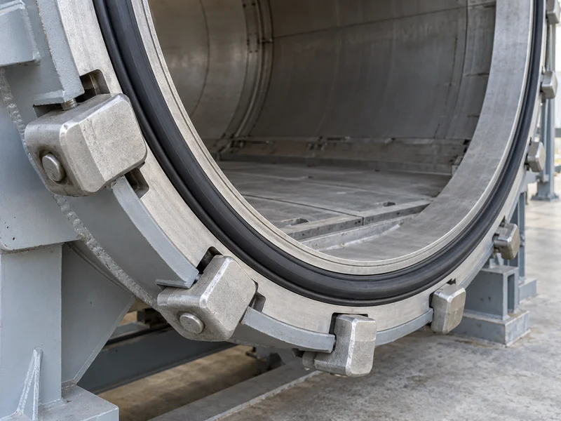
Reserve space for inspecting the closure, working on the seal area and servicing the supporting and actuating components. The manufacturer should define the tasks and access conditions for the supplied assembly. Do not base the allowance only on whether a person can stand beside the door.
Component removal can require more space than routine inspection. Identify the largest expected replaceable assembly and its planned removal route. Check whether permanent pipes, platforms or neighboring equipment would obstruct that route after installation.
How Should Spares and Service Responsibilities Be Specified?
Request identification of the seals, wear parts and mechanism components recommended for the selected duty. Confirm the information needed to order compatible replacements. A generic seal description is less useful than a controlled part reference tied to the supplied door assembly.
Establish which inspections and adjustments require the manufacturer’s service personnel or other qualified specialists. The maintenance documentation should define safe preparation and authorized procedures for the pressure equipment. Layout planning should support those procedures without attempting to replace them.
Which Safety and Acceptance Questions Belong in Procurement?
Review door locking, movement and protective controls together with the vessel manufacturer. Obtain the manufacturer’s description of the interlocks, operating permissions and required inspection provisions. Assign the project specialists to identify the pressure-vessel rules and approval steps that govern this site.
Agree how the supplied door, loading equipment and controls will be demonstrated during acceptance. The demonstration should use the approved procedures and verify the documented interfaces. It should also confirm that the installed surroundings preserve the specified access and movement clearances.
For an existing factory, base this review on measured site conditions. Photographs can help explain obstructions, but they do not replace dimensions and elevations. Record any building or utility changes needed before equipment delivery.
How Can Buyers Make the Final Door Selection?
Compare the offered door arrangements using the same load, vessel layout and maintenance assumptions. Include the mechanism envelope, operator access, component removal and any required building changes. The preferred option is the one that fits the complete operating and service arrangement with clearly assigned responsibilities.
For a Runding proposal, provide the vessel row layout, loading direction, available building height and nearby service routes. Request the selected door configuration on the coordinated drawings before approving manufacture. This turns a broad choice between side and upward opening into a reviewable plant interface.