
AAC mould size affects compatibility through more than the volume of slurry it can hold. The mould’s internal cavity, external frame, side plate, lifting points and operating orientation must match pouring, precuring, demoulding, cutting and downstream handling. Choose the mould format as part of the production line design, and verify every transfer interface before ordering a replacement or a larger format.
Which Dimensions Define the Mould Format?
Separate internal working dimensions from external equipment dimensions. Internal length, width and height describe the space available for the cake, while external dimensions determine clearances and contact with handling equipment. A supplier’s shorthand size may describe only one of these envelopes.
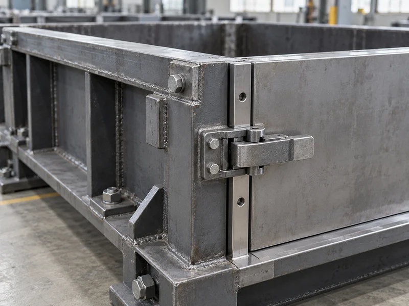
Request a dimensioned drawing with a defined orientation and reference surfaces. Include the frame, side plate, locks, wheels or support features, lifting connections and any projections. Two moulds with the same nominal cavity can still require different handling arrangements.
Begin by identifying a candidate format in the mould and side plate range. Use it to identify the intended family, then obtain the project drawing and its tolerances. Do not treat matching catalogue dimensions as confirmation that a new mould will run on an existing line.
Does a Larger Cavity Mean More Saleable Output?
A larger cavity can hold a larger cake, but daily saleable output depends on the whole route. The casting schedule, precuring space, cutting throughput, curing arrangement and packing capacity must all support the change. Extra volume in one mould may simply move the restriction to another station.
Distinguish nominal cavity volume, pouring quantity, expanded cake dimensions and finished saleable volume. They are not interchangeable quantities. The process designer should define how the chosen recipe and operating allowances connect these figures.
When comparing formats, ask for a production calculation using the intended product mix. Include trimming and product layout rather than multiplying gross cake volume by a theoretical cycle count. Show assumptions separately so that yield improvements are not confused with a larger equipment envelope.
How Does Mould Size Affect Pouring and Precuring?
Check whether the batching and pouring arrangement can deliver the required charge within the intended cycle. A different mould format may require review of batch size, discharge position and the way material is distributed. The assessment belongs to the proposed recipe and equipment, not to a universal filling percentage.
The mould must also travel through precuring without conflicting with doors, rails, transfer cars or adjacent positions. Check the full outer envelope and the orientation used during movement. Include room for inspection and normal handling operations instead of placing moulds only as tightly packed rectangles on a layout.
Do not assume that changing the cavity leaves the precuring process unchanged. The supplier should review the resulting cake condition and readiness for handling under the proposed operating conditions. Confirm both the available positions and the time each mould occupies them.
What Must Match at Demoulding?
The crane or demoulding device must engage the mould at the intended locations and support the relevant load in every required position. Check connection geometry, locking sequence, clearances and load information together. The load rating must be checked alongside those mechanical interfaces.
For a tilting process, the movement envelope includes the mould and cake throughout rotation. A component that fits at the start and end can still conflict with a nearby structure during the movement. Ask for the operating envelope on the layout and identify who checks it against the building and adjoining equipment.
Also confirm the interface between mould frame and side plate. The plate must locate consistently and release according to the equipment’s intended sequence. Mixing similar-looking frames and plates from different designs without a checked interface drawing can introduce alignment or sealing problems.
How Should the Cutting Interface Be Checked?
The cutting system must accept the cake dimensions, support arrangement and orientation produced by demoulding. Verify the available travel, wire arrangement, trimming allowance and transfer clearances. A claim that a cutter handles a certain length does not establish that every mould of that length is compatible.
Review the AAC block cutting machine alongside the mould proposal. Provide the intended block sizes and explain which product changes are expected during a shift. The supplier should identify the achievable cutting layouts and any setup changes required for each format.
Distinguish changing the cut pattern within an accepted cake envelope from changing the cake envelope itself. The former may be handled by an approved machine adjustment, while the latter may involve supports, transfer equipment and control changes. Obtain a specific scope for the proposed change rather than relying on the word flexible.
| Interface | Dimensions and Conditions to Verify |
| Pouring position | Cavity location, charge delivery and surrounding clearance |
| Demoulding device | Engagement points, load, locking and movement envelope |
| Cutting station | Cake orientation, support references and usable travel |
| Curing transport | Side plate supports, loaded envelope and carrier arrangement |
| Return route | Cleaning, inspection, transfer and storage positions |
Why Does the Side Plate Matter Beyond Cutting?
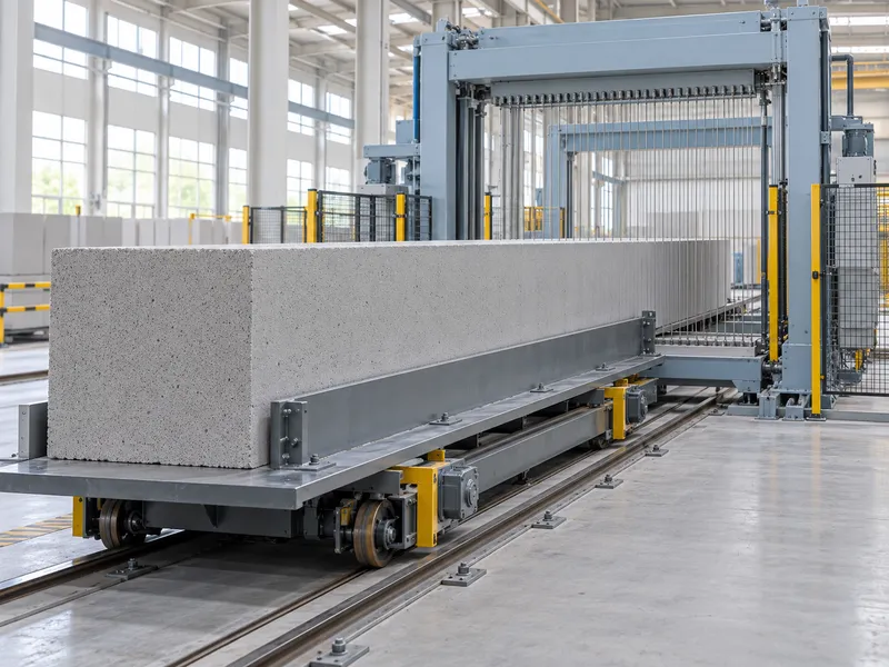
Follow the side plate through the actual process route. In the relevant tilting arrangement, it supports the cake after demoulding and interfaces with later handling stages. Its dimensions and support features therefore connect several machines that may have been quoted separately.
Confirm which surfaces locate the plate and which carry its load at each station. Ask the line supplier to define the permissible condition of those surfaces and how it will be checked. A component may be nominally the correct size yet fail to sit consistently because its working references are damaged or outside tolerance.
Review the loaded envelope on curing transport rather than checking only the empty plate. Account for the intended cake arrangement, supporting equipment and required clearances. The autoclave loading plan must be checked for the selected format; fitting through the door is only one part of that review.
Can Existing Moulds Be Reused in an Expansion?
Reuse is possible only when the existing equipment’s actual condition and interfaces meet the new line’s requirements. Begin with identification and measurement of the available moulds and plates. Drawings are useful, but they should be reconciled with the equipment that will be transferred.
Have the new line supplier classify each existing component as reusable, adaptable or unsuitable for the proposed installation. Include the effects on control sequences and handling equipment. A proposal that excludes adaptation work may appear inexpensive while leaving essential integration unresolved.
Keep different mould families identifiable if the plant intends to operate more than one. Define which routes and recipes permit each family and how an incompatible unit is prevented from entering a station. Specify the identification and routing controls jointly during the line design review.
What Should a Trial Demonstrate Before Final Acceptance?
A useful trial follows the agreed mould format across all relevant interfaces. Check engagement, positioning, transfer, cutting and return under the defined test conditions. An isolated measurement of the empty cavity cannot demonstrate an integrated production route.
Use the intended product layouts to verify the cutting result and downstream handling. Record any temporary adjustments used during the trial and decide whether they belong in the final operating procedure. Do not allow an improvised workaround to become an undocumented condition of normal production.
For an existing plant, agree the verification sequence and responsibilities before installation. Establish which checks can be completed with drawings or gauges and which require an equipment trial. This makes the shutdown plan more credible and reduces the chance that a missing interface emerges after the old equipment has been removed.
What Information Should Accompany the Purchase Order?
Attach approved mould and side plate drawings, the interface schedule and the agreed operating envelope. Reference the actual revision used for fabrication and acceptance. For every proposed drawing change, record its consequences at adjoining stations and assign the necessary follow-up work.
- State internal dimensions, external dimensions and reference orientation.
- Specify load information and verified handling connections.
- List the product formats and cutting arrangements included.
- Identify the curing transport and return-route interfaces.
- Document tolerances, inspection methods and acceptance conditions.
Ask Runding to review the mould format against the complete proposed route rather than quoting moulds as independent containers. That review should produce a clear list of compatible interfaces and any required changes. The resulting purchase decision is based on usable production capability, with the mould size supported by the equipment around it.