
AAC slurry pumps continuously transfer material across preparation, storage, batching, mixing, and casting, where changing density creates demanding operating conditions.
Troubleshooting should examine slurry properties, liquid level, pipelines, mechanical condition, and production demand before replacing components or increasing motor power.
Operating Conditions
- Slurry concentration: Determines resistance, motor load, and sedimentation tendency.
- Particle condition: Influences impeller wear, blockage risk, and passage requirements.
- Liquid level: Affects pump immersion, suction stability, cooling, and continuous operation.
- Pipeline length: Changes total resistance and usable discharge capacity.
- Vertical height: Determines the head required from the selected model.
- Operating frequency: Influences motor temperature, bearing load, and restart reliability.
- Process rhythm: Determines whether the pump must work continuously, intermittently, or in short batching cycles.
Slurry Pump Problem Diagnosis
The initial check shall separate process faults and mechanical defects. Reduced flow caused by thick slurry requires a totally different handling approach versus flow loss resulting from excessive impeller wear.
| Problem | Signal | Check | Action |
| No discharge | Motor runs, no flow | Level, rotation, inlet | Stop and inspect |
| Low flow | Slow slurry transfer | Density, pipe, impeller | Compare normal flow |
| Unstable flow | Pulsating discharge | Level, air, sediment | Stabilize inlet conditions |
| Low head | Slurry cannot reach outlet | Lift, resistance, wear | Check required head |
| Blockage | Sudden flow reduction | Elbows, pipes, particles | Flush blocked sections |
| High current | Motor load rises | Density, impeller, bearing | Stop and inspect |
| Vibration | Pump shakes | Impeller, shaft, fasteners | Check alignment |
| Abnormal noise | Grinding or knocking | Bearing, impeller, debris | Stop immediately |
| Bearing heat | Housing overheats | Lubrication, clearance | Service bearing assembly |
| Rapid wear | Short component life | Abrasiveness, operating point | Reassess configuration |
Problem 1:No Slurry Discharge After Startup
Immediate inspection is needed for slurry pumps with normal startup but zero output. Long-time idle or dry running will easily trigger overheating, wear of the impeller and excessive mechanical friction.
Incorrect Motor Rotation
- Signal: Motor operates normally, but no slurry reaches the discharge point.
- Inspection: Observe the motor direction before connecting the pump coupling device.
- Treatment: Correct the electrical phase sequence and confirm the designated rotation direction.
Slurry Below the Minimum Level
- Signal: Flow disappears as the slurry tank approaches empty.
- Inspection: Check whether the pump inlet and working section remain sufficiently immersed.
- Treatment: Stop the pump immediately and restore the specified slurry level before restarting.
Inlet Passage Covered by Sediment
- Signal: Motor runs, but discharge remains weak or absent after a long shutdown.
- Inspection: Check sediment around the lower pump body and impeller inlet.
- Treatment: Agitate the tank, remove hardened deposits, and clean the inlet passage.
Impeller Passage Blocked
- Signal: Pump starts with abnormal load, little discharge, and possible vibration.
- Inspection: Open the pump body and inspect the impeller passages.
- Treatment: Remove hardened slurry, foreign objects, or oversized particles.
Problem 2:Low Slurry Flow Rate
Reduced flow capacity is a highly disruptive defect occurring in AAC slurry pumps. Though the assembly line maintains continuous operation, the practical slurry delivery rate slowly declines and no longer satisfies production specifications.
Slurry Concentration Above the Normal Range
Possibilities: Flow reduction / Current increase / Slower batching / Dense discharge
The first step is to compare:
- Current slurry density with the normal formula
- Current transfer time with previous batches
- Motor current with the established operating range
- Tank agitation condition
- Water addition and raw-material feeding records
Impeller Wear
Possibilities: Rounded edges / Enlarged clearance / Lower flow / Reduced head
Impeller wear should be evaluated by comparing:
- Discharge time
- Delivered volume
- Outlet pressure
- Motor current
- Impeller dimensions
- Clearance between rotating and stationary parts
Excessive Pipeline Resistance
Possibilities: Long pipe / Multiple elbows / Reduced diameter / High vertical lift
A practical inspection sequence is:
- Check whether all valves are fully open.
- Inspect flexible connections for internal collapse.
- Examine elbows for sediment accumulation.
- Confirm that no later modification reduced pipe diameter.
- Measure the actual vertical difference.
- Compare the installed conditions with the selected pump head.
Outlet Pipe Leakage
Small flange gaps, worn joints, or damaged gaskets reduce slurry delivery, create deposits, complicate cleaning, and make later maintenance difficult.
Problem 3:Unstable or Pulsating Slurry Delivery
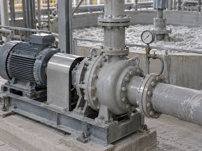
The batching system needs repeatable material delivery, so merely maintaining a stable average flow is inadequate. Slurry flow pulsations result in inconsistent weighing cycles and irregular filling.
Fluctuating Tank Level
If the tank level changes quickly, the operating condition around the pump changes with it. Flow may appear stable near the middle level but become irregular near the minimum level.
Treatment direction: Maintain a controlled operating range rather than allowing the tank to repeatedly move between full and nearly empty.
Air Entering the Flow
Air pockets may enter when the liquid level is low, agitation is too aggressive near the pump, or the inlet zone forms a vortex.
Operating signs:
- Irregular outlet flow
- Intermittent vibration
- Sudden reduction in current
- Bubbling in the receiving tank
- Repeated loss and recovery of discharge
Uneven Slurry Concentration Inside the Tank
Uneven tank concentration makes the pump alternate between dense and thin slurry. Proper agitator blade position, speed, tank geometry, and pump placement maintain uniform mixing and stable loads consistently.
Problem 4:Insufficient Discharge Head
Even if a slurry pump works to transport materials, it may not feed slurry into designated tanks, mixers or overhead pipes. This malfunction stems from inadequate head rather than full flow breakdown.
Actual Head Exceeds Pump Capability
Pump selection must account for lifting height, pipeline resistance, elbows, valves, slurry concentration, and outlet conditions to maintain required flow.
Head Loss Caused by Wear
A pump that previously completed the transfer may gradually lose head as the impeller and pump body wear.
Diagnosis: Compare current operating results with the original commissioning record under similar slurry conditions.
Partial Blockage
A partially restricted outlet can produce both low flow and insufficient head. Pressure may increase before the blockage while useful delivery decreases after it.
Elbows deserve particular attention because dense particles change direction there and can accumulate during shutdowns.
Problem 5:Slurry Blockage and Sedimentation
The location and timing of the blockage usually indicate the operating condition that produced it.
| Blockage Position | Cause | Solution |
| Impeller Inlet | Settled slurry | Clean inlet; start agitator first |
| Impeller Passage | Large particles or hardened slurry | Remove deposits; improve screening |
| Pump Elbow | Dense slurry buildup | Flush elbow; reduce residue |
| Connecting Pipe | Slurry settles after shutdown | Flush pipe after operation |
| Outlet Pipe | Low flow velocity | Clean pipe; review diameter |
| Valve Area | Restricted valve opening | Clean or replace valve |
| Receiving Inlet | Hardened discharge buildup | Remove deposits; improve outlet design |
Blockage During Startup
Startup blockage often develops after the pump and pipeline remain filled with slurry during a production stop.
A reliable startup sequence includes:
Tank agitation → slurry condition confirmation → valve confirmation → motor direction confirmation → short observation run → normal transfer
Blockage During Normal Operation
A sudden blockage during stable production may indicate:
- Foreign material entering the tank
- A collapsed flexible connection
- A partly closed valve
- A detached internal component
- Rapid concentration increase
- Hardened deposits breaking loose upstream
Do not repeatedly restart the motor. Repeated starting can increase electrical and mechanical load without clearing the restriction.
Blockage After Shutdown
Drain or wash all pipelines after stopping operation. Clear leftover slurry settled in low areas, bends, valves and horizontal pipes to stop the material from hardening.
Problem 6:Motor Overload and High Current
Technicians can rely on motor current for troubleshooting, since this parameter reveals the load exerted on the rotary assembly.
High Slurry Density
Dense slurry increases resistance against the impeller. If high current appears at the same time as slower flow, inspect slurry concentration before dismantling the motor.
Mechanical Drag
Mechanical resistance may come from:
- Impeller rubbing against the pump body
- Bent shaft
- Damaged bearing
- Incorrect bearing assembly
- Excessively tight seal gland
- Foreign material trapped between rotating parts
- Misalignment in the coupling device
Rotate the shaft manually only after isolating electrical power and confirming safe access.
Operation in Settled Material
Compacted slurry causes high startup current; increasing motor power without better agitation shifts loads to shafts, impellers, bearings, and casings.
Incorrect Voltage Condition
The slurry pump power system can be configured for 380 V, 400 V, 415 V, 440 V, 460 V, 480 V, 600 V, or 660 V, with customized options available. The supplied motor and control system must match the plant voltage.
Voltage mismatch, unstable supply, or incorrect overload settings can create heating and unreliable starting even when the hydraulic side is acceptable.
Problem 7:Motor Overheating
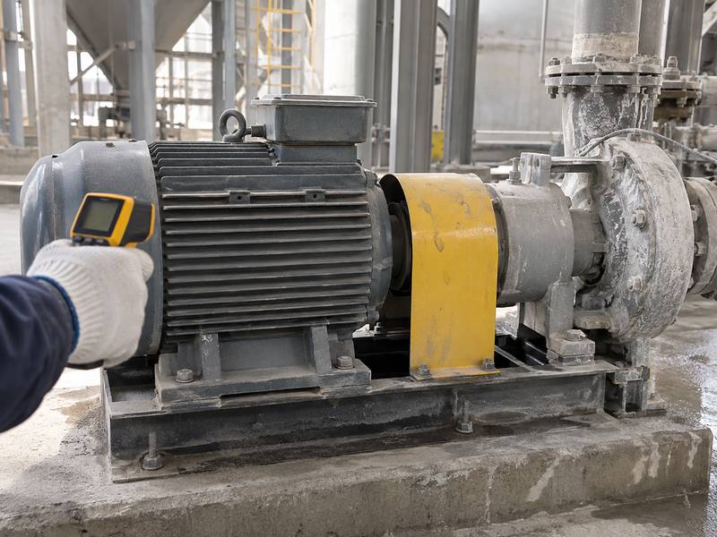
To judge the root cause of excessive motor temperature, technicians need to analyze operating current, continuous running period, site environmental parameters as well as the frequency of equipment startup jointly.
Continuous Operation at Excessive Load
A motor might not draw enough current to trigger an immediate shutdown, yet running close to its load ceiling for extended time will cause its temperature to climb steadily.
Instead of merely checking motor temperature post startup, record thermal readings across the whole production run.
Excessive Start-Stop Frequency
AAC batching may require repeated short transfers. Frequent starts create higher thermal stress than steady operation.
Liquid Depth of 2.5–3 m
The product instructions specify intermittent operation when liquid depth reaches 2.5–3 m. This condition should be included in the control strategy rather than left to operator judgment.
Poor Heat Dissipation
Dust, slurry coating, restricted ventilation, and an enclosed motor area can reduce heat dissipation. Clean the motor frame and maintain sufficient surrounding space.
Problem 8:Pump Vibration
Impeller Imbalance
Uneven wear or adhered material changes the mass distribution of the impeller. Vibration may increase at operating speed while remaining less obvious during manual rotation.
Shaft Deformation
Heavy blockages, foreign matter strikes, faulty assembly or running with a loosened impeller all have the potential to bend the pump shaft.
Measure shaft runout and confirm bearing fitting integrity before fitting a replacement impeller.
Bearing Damage
Its structural assembly consists of double-row tapered roller bearings paired with single-row cylindrical roller bearings. These components support the shaft under combined operating loads.
Loose Fixing Plate or Motor Frame
Inspect the fixing plate, motor frame, bracket, pump body bolts, and pipeline supports. A secure pump cannot remain stable when the connected pipe applies continuous side load.
Pipeline Stress
When pipelines are installed out of alignment, tension will displace the pump discharge port from its designed resting position. It is inadvisable to apply external force through pump connectors to straighten misaligned pipework.
Problem 9:Abnormal Pump Noise
- Grinding sound: Possible impeller contact, hard foreign material, or bearing damage.
- Knocking sound: Loose component, damaged coupling, or large object moving inside the pump.
- Continuous rumble: Bearing deterioration or severe vibration.
- Intermittent rattling: Air entry, unstable liquid level, or loose deposits.
- Sharp friction sound: Seal, shaft, or impeller contact.
Noise should be recorded by operating stage: startup, normal transfer, low-level operation, or shutdown. This helps distinguish internal damage from level-related flow instability.
Problem 10:Impeller and Pump-Body Wear
Abrasive Wear
Sand-rich slurry continuously removes material from the impeller and pump body. Wear becomes faster when particle concentration, velocity, or particle size increases.
Uneven Wear
Uneven wear may indicate an unstable flow path, impeller imbalance, misalignment, or operation outside the intended range.
Wear Caused by Low Flow Operation
Oversized pumps that greatly exceed actual flow demands often operate under throttling or improper working states for extended durations. Internal circulating flow and unbalanced loads will quicken equipment deterioration.
Wear Caused by Frequent Blockage
Repeated blockage and aggressive restarting place additional stress on the impeller connection and shaft.