
Specify an AAC tilting and demoulding crane by its interfaces with the mould, side plate, building, cutting trolley and control system. Confirm how it engages and releases the load, the space required throughout its movement, and the conditions that permit each transfer. A lifting rating and a nominal mould length do not define a complete working installation.
What Sequence Must the Crane Complete?
Start with the plant’s actual handling sequence. In the relevant tilt-cake process, the equipment turns the mould, positions the supported cake for cutting and removes the mould frame. The empty frame and a suitable plate then return through the agreed preparation route.
Draw the sequence as a series of defined equipment states. Identify where the mould arrives, when the cake is supported by the receiving equipment and when the crane may release or move away. The drawing should distinguish actions performed by the crane from actions performed by another station.
Use the tilting and demoulding crane description to establish the proposed supply boundary. Ask the supplier to explain which motions, locking devices, hydraulic components and controls belong to that scope. Resolve gaps between independently supplied machines before detailed design proceeds.
Which Mould Features Must Match the Lifting Device?
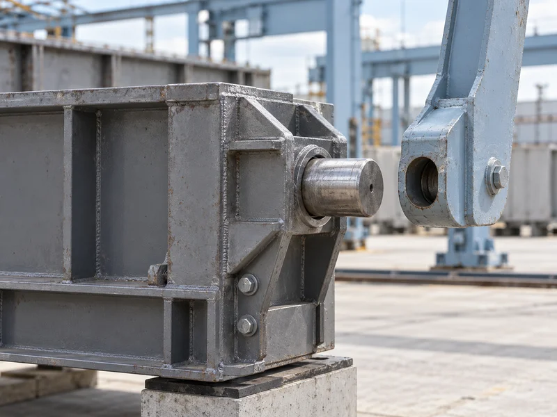
Provide the approved mould and side plate drawings, including the working connection points. Confirm the location, shape and permitted condition of the surfaces or features used for engagement. Overall mould length alone cannot establish whether the lifting device will connect correctly.
Include every mould family that the crane is expected to handle. Identify any differences in connection geometry, plate arrangement or locking method. The supplier should state whether the proposed device accommodates them directly or requires an approved change of equipment.
For replacement projects, measure the existing components and reconcile their condition with the available drawings. Wear, repairs or previous modifications may have altered a working interface. Do not rely on a model label when the machine must engage physical features that have changed in service.
- Define engagement positions from common drawing references.
- Identify mould locks and the required release sequence.
- Specify the plate interface and supported orientation.
- List all intended mould families and change requirements.
- Agree inspection and acceptance of reused equipment.
What Load Information Does the Supplier Need?
Supply the loads associated with each operating state, not just the mass of the empty frame. The relevant assembly may include the mould, plate and green cake, with their actual mass distribution. The crane designer needs sufficient information to assess the complete handling duty.
State the expected range of cake mass and explain how it relates to the production plan. A finished dry product figure may not represent the mass handled before curing. Have the process and mechanical suppliers agree the basis rather than leaving each to assume a different value.
Describe the required operating frequency and movements. A load handled repeatedly throughout a shift creates a different duty from an occasional maintenance lift. Let the equipment designer establish the applicable design provisions from the documented load and cycle requirements.
How Should the Movement Envelope Be Reviewed?
Check the full path of the loaded assembly, including rotation and approach to the receiving station. Show the envelope on the plant layout and building sections. Clearance at two stationary endpoints does not prove clearance between them.
Include the lifting device, mould projections and service connections in that review. Check nearby columns, rails, platforms, cable routes and adjacent equipment against the proposed movement. Assign a single coordinating party to reconcile the crane drawing with the overall plant model.
Maintenance clearance deserves its own review. The installed crane must allow access to the components that require inspection or replacement, with a planned route for removing them. Service space should not be assumed to exist merely because production movements fit.
What Must Match at the Cutting Trolley?
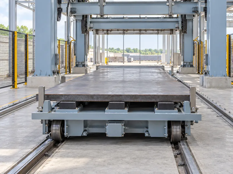
The receiving trolley must locate and support the plate or cake assembly in the position expected by the next operation. Agree its reference surfaces, elevation and approach position with the crane supplier. The handover should have a defined completion state before either machine begins its next movement.
Review the cutting line interface using the same drawing revision as the crane. Identify the required orientation and positioning conditions. If the trolley and crane come from separate suppliers, require a shared interface record instead of two unconnected equipment drawings.
Define the position-confirmation method and the waiting state used when the trolley cannot receive the load. The crane should not rely on an assumed empty trolley or an informal operator signal where the agreed design requires confirmation. The control sequence must reflect the physical transfer arrangement.
| Interface | Required Agreement |
| Mould to lifting device | Connection geometry, load states and permitted component condition |
| Crane to building | Supports, movement envelope and service access |
| Crane to trolley | Receiving position, support references and transfer completion |
| Crane to controls | State signals, permissives, stop response and recovery sequence |
| Frame to return route | Empty-unit destination and readiness for reassembly |
Which Control Signals Need an Interface List?
Document the signals exchanged with the incoming transport, cutting trolley and return equipment. For each signal, state its meaning, source and the action it permits or prevents. A list of spare inputs and outputs does not explain the required operating sequence.
Have the responsible controls and machinery designers establish the necessary protective functions. The project review should cover relevant conditions such as incomplete engagement, an occupied receiving position or an interrupted movement. Specify the required response and verification method rather than prescribing generic logic for an unknown machine.
Clarify behaviour after a stoppage. The system must determine the actual equipment and load state before the approved recovery sequence proceeds. A restart instruction should not silently assume that a transfer was completed when power or a signal was lost.
Agree how alarms identify the affected station and condition for operators. Useful fault information reduces time spent guessing whether the problem lies in the crane, mould or receiving equipment. Include operator training and the controlled recovery procedure in the delivery scope.
Which Utilities and Installation Responsibilities Must Be Defined?
Confirm electrical and hydraulic supply boundaries for the quoted arrangement. List the equipment supplied with the crane and the connections the site must provide. The drawings should identify locations that allow installation and service without interfering with movement.
Have the relevant engineers confirm structural supports and installation requirements. Foundation or runway information needs to match the supplied equipment and its design loads. Do not substitute a general building allowance for the crane supplier’s project data.
Assign responsibility for mechanical alignment, cable installation, control integration and commissioning checks. Interfaces often remain unresolved when each quotation assumes another contractor will complete them. Record deliverables and acceptance responsibilities in the equipment schedule.
How Should Buyers Define the Cycle-Time Requirement?
State the required interval between successive completed handovers and the conditions under which it must be achieved. Include the mould arrival pattern and the receiving station’s availability. An isolated rotation time does not show the sustained output of the full sequence.
Ask the supplier to identify which activities overlap and which must occur in order. Account for engagement, transfer, release, empty-frame handling and return as applicable. The agreed timing model should explain how the crane fits the production schedule without assuming that every other station is always ready.
Keep cake readiness within the process requirements. A demand for a faster crane cycle should not lead to handling a cake before it is suitable for the proposed operation. Separate a mechanical capacity problem from a process-readiness delay during performance review.
What Should Be Demonstrated Before Handover?
Verify the agreed interfaces using the intended moulds, plate arrangement and receiving equipment. Record the load and operating conditions of the trial. Check repeatable positioning, normal sequence completion and the approved responses to testable fault conditions under the supplier’s commissioning procedure.
Inspect the cake and its support after representative transfers according to the plant’s quality plan. If damage or inconsistent positioning appears, investigate the interface conditions before accepting repeated manual correction as normal practice. Record any adjustments in the final drawings and operating documents.
Provide Runding with the mould drawings, layout and production schedule when requesting a crane proposal. A complete specification connects the load to the lifting device, the movement to the building and the handover to the next machine. That evidence is what makes the proposed crane assessable as part of the AAC line.